01 / Cutting
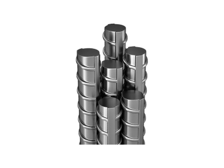
The bar end is cut square at 90°.
A sawn face, not a sheared one. Both bars have to seat flat against each other inside the coupler, and any angle left on the end shows up later as a gap the thread has to close.

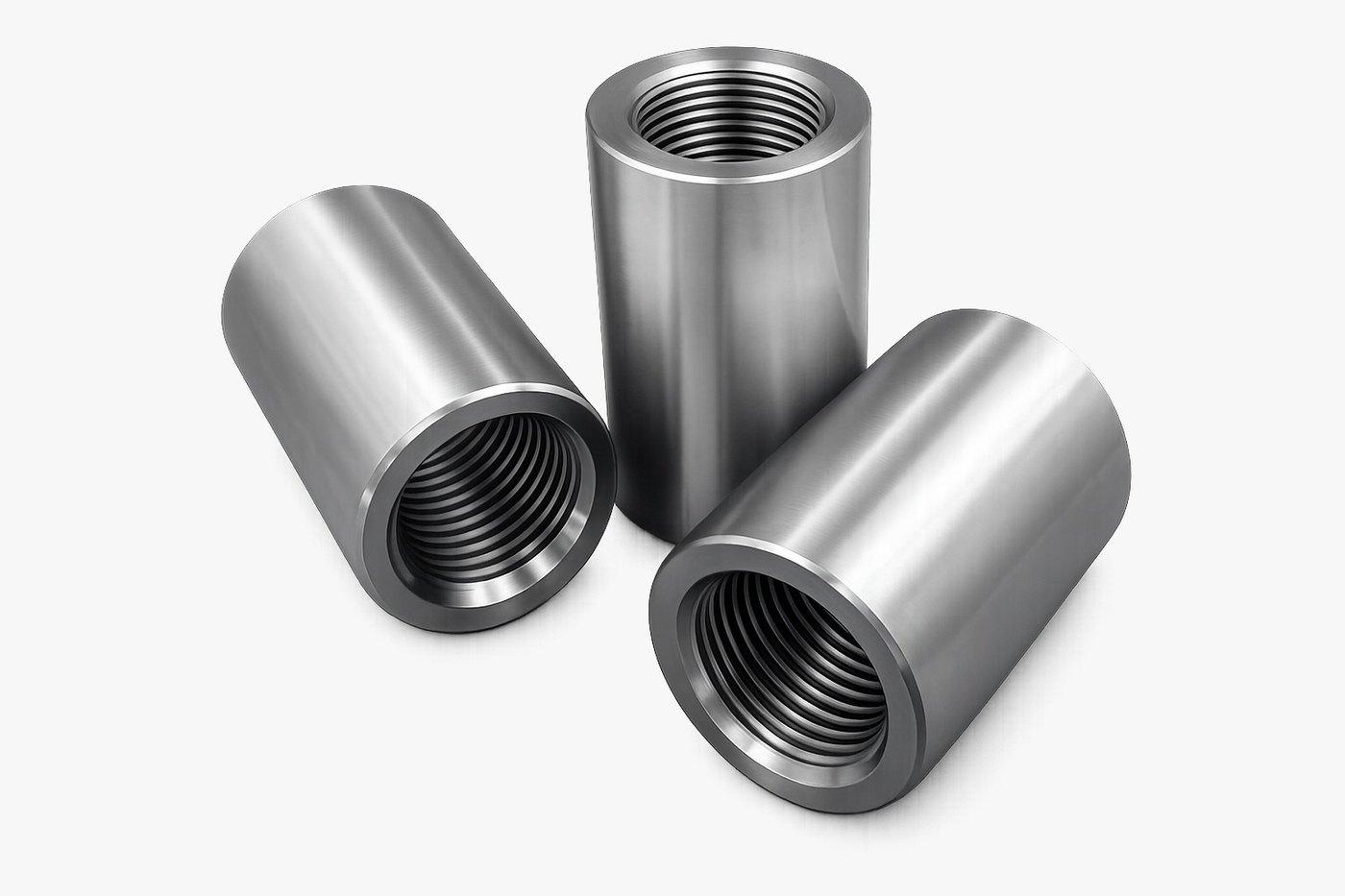
Parallel-threaded couplers for bars 12 to 40 mm. Full ductile strength with no reduction in the bar section.
The standard coupler covers the whole range, from 12 mm up to 40 mm, in one thread form. Both bars are threaded the same way and the sleeve is turned on until it seats, so there is no torque wrench to calibrate and nothing to read off a gauge on site.
Because the bar end is forged before it is threaded, the thread is cut into added material rather than into the parent bar. The splice is not a reduced section, which is why the joint develops the bar rather than governing it.
Every bar that goes through our Rajkot works passes the same sequence in the same order — and the third operation is only reliable because of the second.
A sawn face, not a sheared one. Both bars have to seat flat against each other inside the coupler, and any angle left on the end shows up later as a gap the thread has to close.
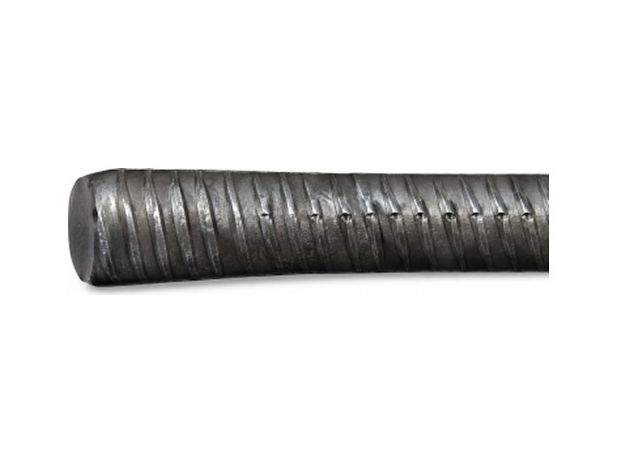
This is the step that matters most. Forging the end oversize first means the thread can be cut into added material rather than into the parent bar, so the splice is never the weak point in the run of steel.
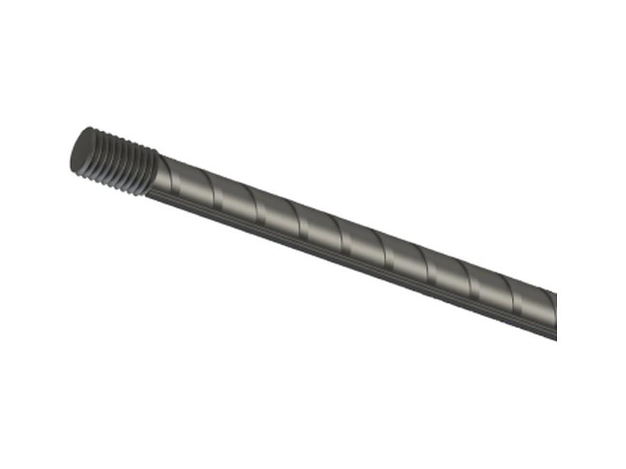
Cut on the enlarged section to the standard RebarConnect parallel thread, then gauged. A parallel thread carries load evenly along its full engagement instead of wedging like a taper.
Each finished end is then checked in tension before it leaves the works. The load is held inside the elastic range, so the test proves the thread without spending the bar — the same end that is tested is the end that ships.
| Size | Length (mm) | OD (mm) | Pitch |
|---|---|---|---|
| 16 mm | 32 | 28 | M 19 × 2.5 |
| 20 mm | 40 | 32 | M 24 × 2.5 |
| 25 mm | 50 | 40 | M 29 × 3.0 |
| 32 mm | 64 | 50 | M 36 × 3.0 |
| 40 mm | 80 | 63 | M 45 × 3.5 |
| Size | Length (mm) | OD (mm) | Pitch |
|---|---|---|---|
| 16 mm | 40 | 25 | M 17 × 2.5 |
| 20 mm | 50 | 32 | M 21 × 2.5 |
| 25 mm | 60 | 40 | M 26.5 × 3.0 |
| 32 mm | 72 | 50 | M 33.5 × 3.0 |
A coupler earns its place wherever the reinforcement is too heavy, the joint too congested, or the pour too far apart in time for an overlap to be practical.
Column and shear-wall bars are joined floor by floor with no lap, so the cage stays open enough to place and vibrate concrete properly.
Piers, pier caps and decks are poured in stages. The thread waits under a cap and the next pour connects at full bar strength.
Viaducts, track slabs and station boxes, where every splice is inspected and has to carry documentation to the project authority.
The joint develops the bar, so force passes between bars instead of through the concrete around a lap.
No hot work, no welder qualification, no heat-affected zone to argue about in an inspection.
A lap doubles the steel at exactly the busiest point of a column. One sleeve does not.
Lap length is steel bought, cut, bent and tied purely to be overlapped. A coupler removes it from the order.
Thread, cap, deliver. On site the bar is offered up and turned in — no measuring out a lap.
Threads are cut to one standard and tested, so the joint made in month nine matches the joint made in month one.